Find more details on U.S. field telephone history on the U.S. Signal Corps Field Telephones Timeline.
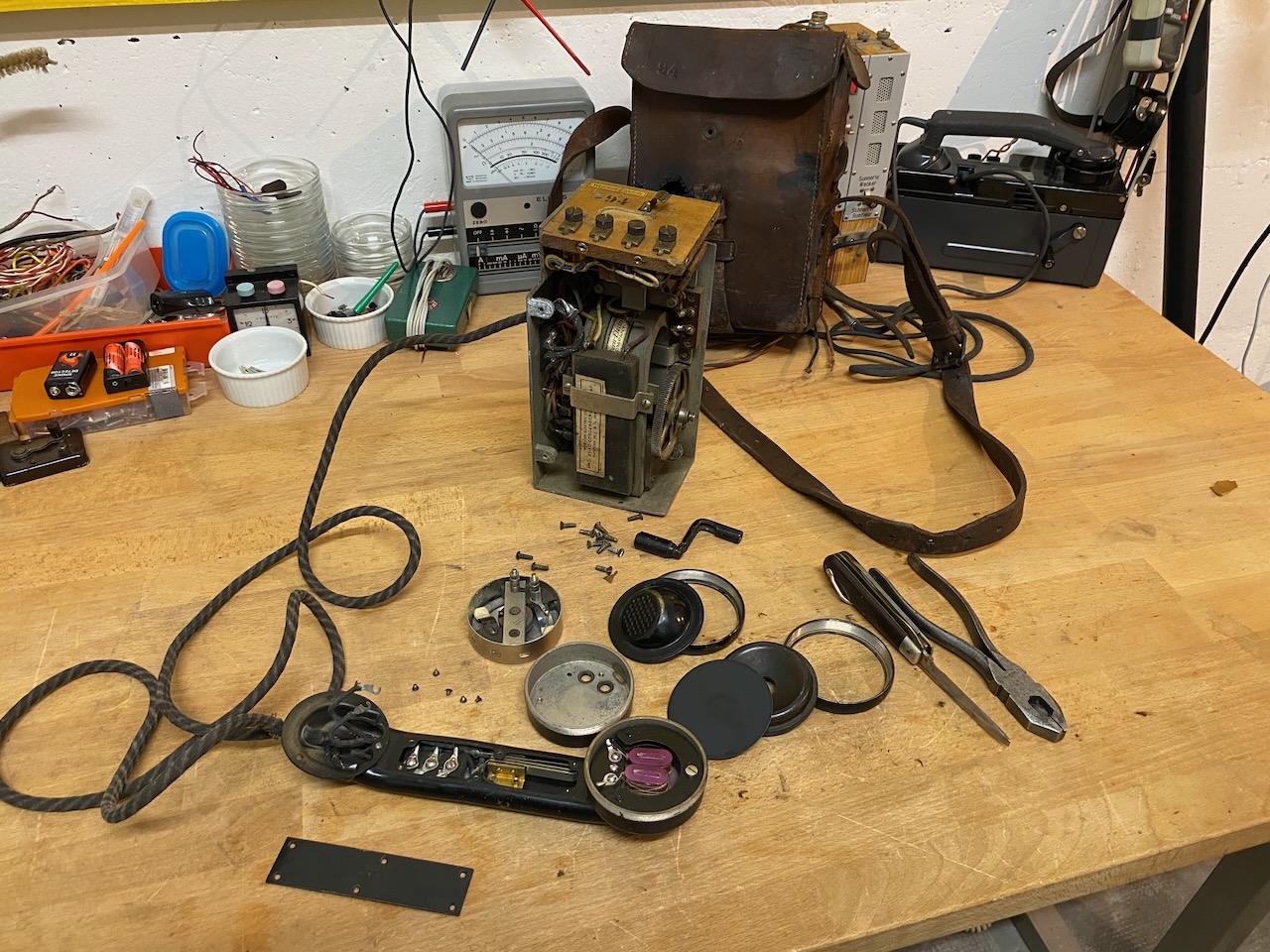
The lightweight EE-5, based on the Western Electric standard model 1375-B, was introduced for use by field artillery units [2][4][5][6]. Unlike the Signal Corps EE-5, the Western Electric 1375-B is listed in the company's catalogues as having no capacitor. The 1375-B appears in Western Electric catalogues from 1916 to 1935, suggesting that the model remained largely unchanged for nearly two decades [1][7]. As none of the components in my example bear a clearly identifiable date, it could have been manufactured at any point during this period.
The Western Electric type 1375 telephone with leather case (type EE-5) was originally designed for the Forestry Service. With a few modifications it was adopted for mobile artillery use and on account of its light weight became popular as a lineman's test set [9].
The EE-5 remained in service well into World War II. Under the Lend-Lease program, approximately 1,000 units were supplied to Mexico, alongside the EE-3 and EE-4. The EE-5 was still listed in the 1939 and 1942 editions of Field Manual FM 24-5 [8][10]. It was the direct predecessor of the EE-8, which retained the same basic arrangement: a bag-type carrying case, an upright chassis, and a handset stored on its side. The French Army also adopted the instrument under the designation “Poste Microtéléphonique, Western Electric Co. type Serbe.” During World War II, the EE-5 gradually became obsolete as it was superseded by the EE-8, and surplus units were subsequently sold to the public [31].
Telephone, Type EE- 5 (From Electrical Engineering Pamphlet No. 3., 1918 [2]):
The type EE-5 telephone (W.E. 1375-B) is a magneto type, local battery, light weight, portable set enclosed in a leather case. It is designed for use on metallic or grounded lines and is capable of ringing a bell or operating a monocord switchboard line signal through high resistances. The principal difference between this set and the type EE-3 telephone is that it is provided with no hook with which to cut the battery off the primary circuit when the set is not in use. Substituted for the hook switch , is a push button in the hand set which must be held down all the time during either talking or listening. There is also no provision in this set for sending messages by buzzer signaling. Practically all of the type EE-5 telephones supplied to date have a condenser in series with the bell windings. This arrangement of the circuit has recently been changed so that this condenser is now placed in series with the receiver [...]. This permits the receiver to be connected across the line at all times. To accomplish this connection, two receiver contact springs in the hand set are strapped together [...]. These changes enable the operator to listen in on the line at all times without having to hold the push button on the hand set down. But he must hold the button down while talking. The parts of the set are mounted on an aluminum frame, the whole set being held firmly in place by ten screws which extend through the leather case and engage the frame casting. These parts include a two-bar or three-bar magneto, 2150-ohm call buzzer instead of a bell, a .5-mfd. condenser in series with the buzzer windings, an induction coil or telephone transformer, a small hard rubber connection block for the three wires leading to the hand set, and a simple lightning protector. [...] The lightning protector consists simply of two brass screws mounted on a small block of hard fiber with about 1/4-in. air gap between them. [...] For most satisfactory operation, a new battery should be installed about every four months whether the instrument has been used or not. The battery should always be tested before taking the telephone out for field service even though it has been stored but a short time. If there is any doubt about the battery, install a new one.
Binding posts for external battery.
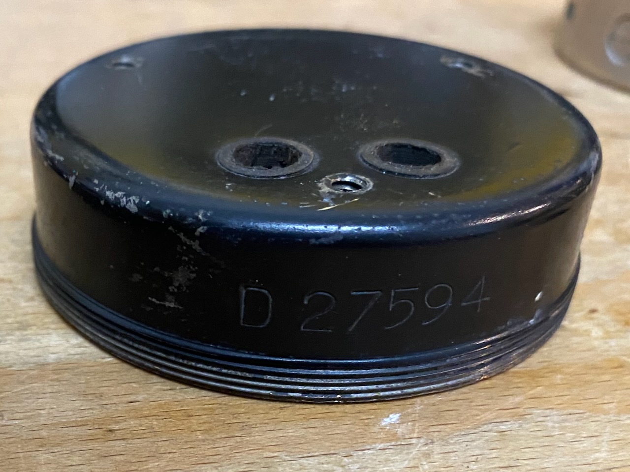
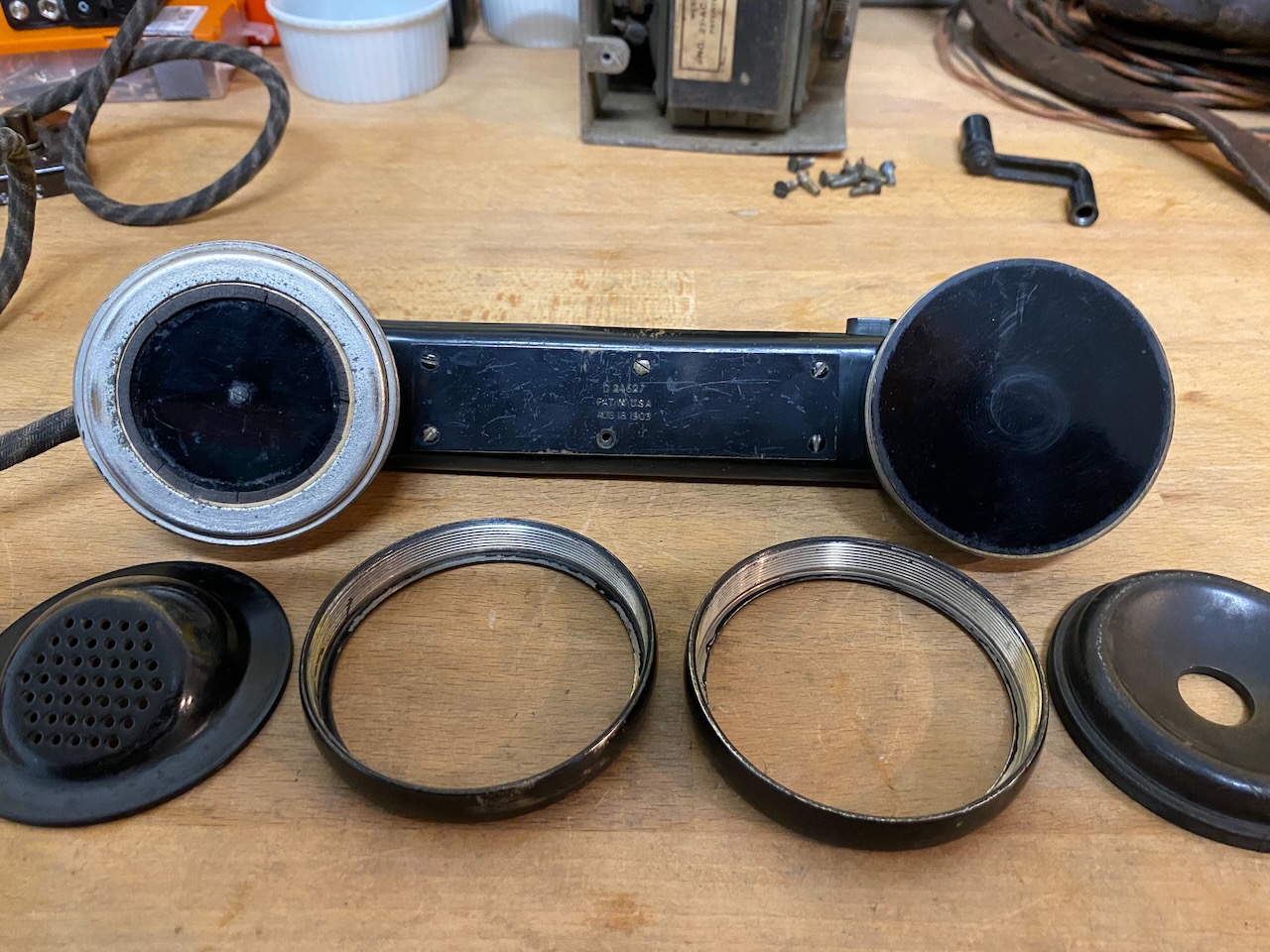
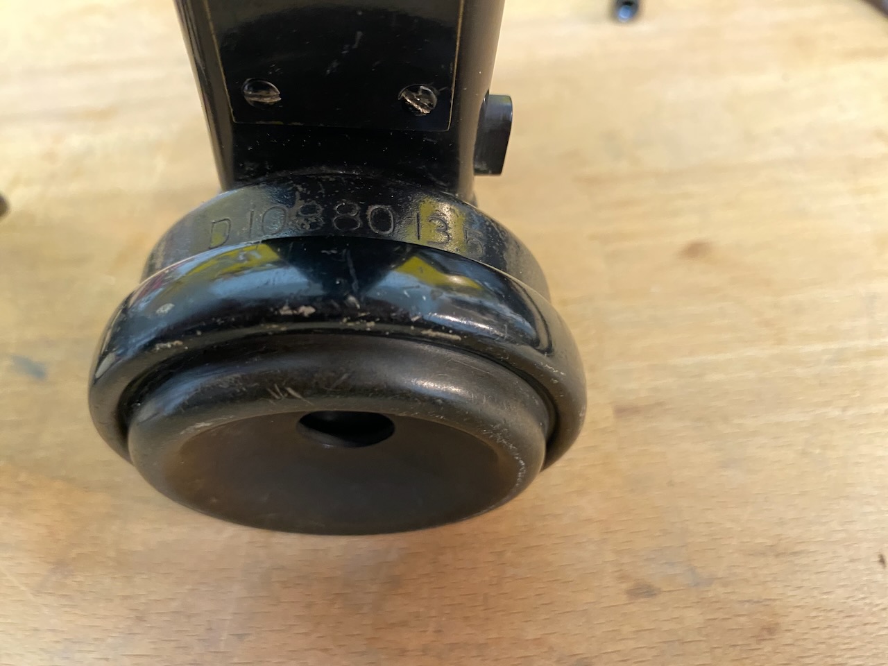
Several EE-5 components bear what i call D-Numbers: D14089 for the complete set, D21141 for the ringer assembly, D24627 for the handset, D27549 for the transmitter, and D10880135 for the receiver. Similar numbers can be found on the EE-4 (Camp Telephone Model A, complete set D12839) and the EE-3 (Field Telephone Model 1917, complete set D14205). These numbers are not mentioned in the military manuals I have consulted. Western Electric seems to have used D-prefixed drawing numbers for various instruments and components, suggesting that the markings may refer to original design drawings rather than military stock numbers [32]. Interestingly, EE-3 and EE-4 sets manufactured by both Western Electric and Kellogg carry the same D-Numbers. The precise significance of these markings on the early field telephones remains uncertain. If anyone has further information, please get in touch.
Disassembled.
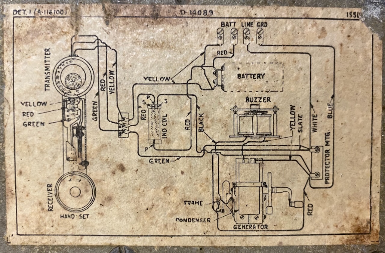
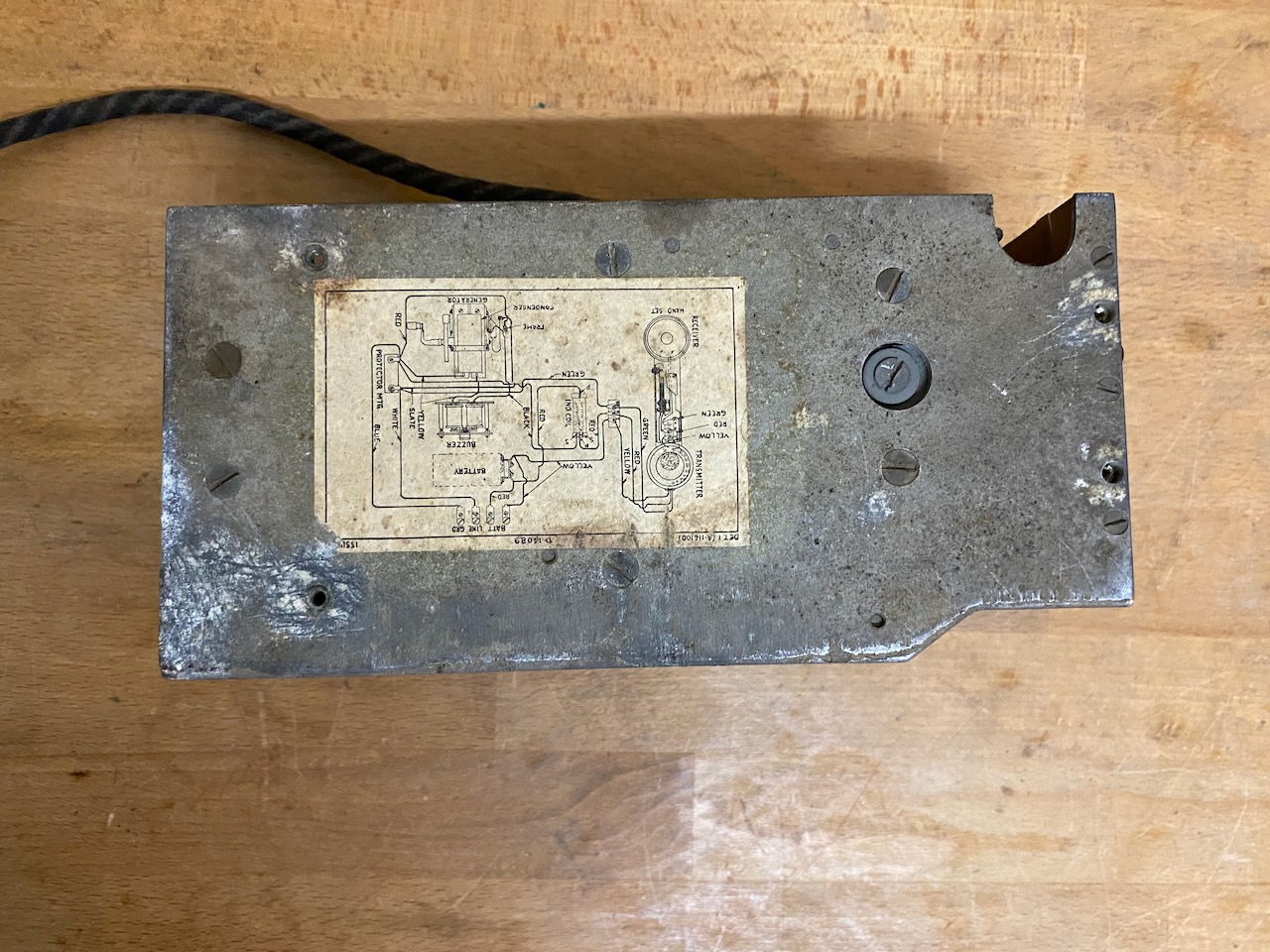
Wiring diagram attached to the instrument chassis.
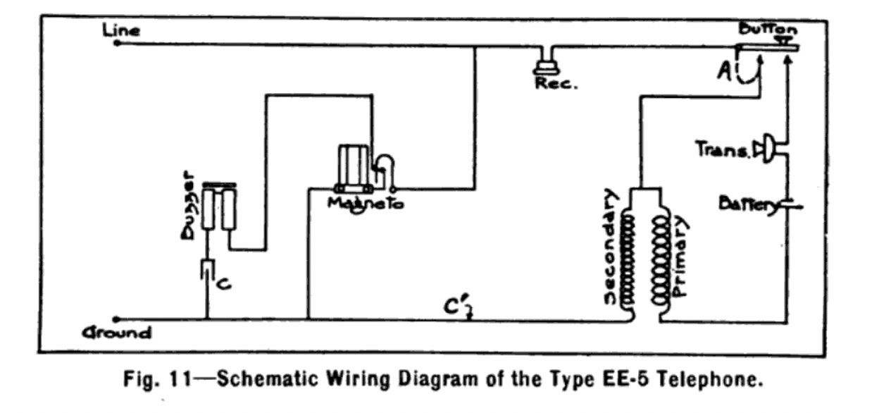
Although my set has the modified capacitor arrangement (apparently applied to most instruments, according to the literature [2]), the diagram was not updated to reflect this modification.
Circuit diagram from Electrical Engineering Pamphlet No. 3 [2].
The modified capacitor arrangement is marked C', while the corresponding modification to the handset switch is indicated by the dashed line at A.
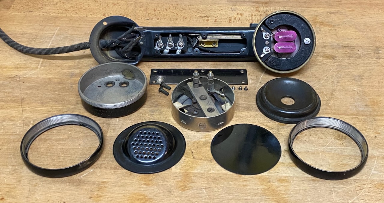
Disassembled handset.
Terminal block and switch inside handset handle.
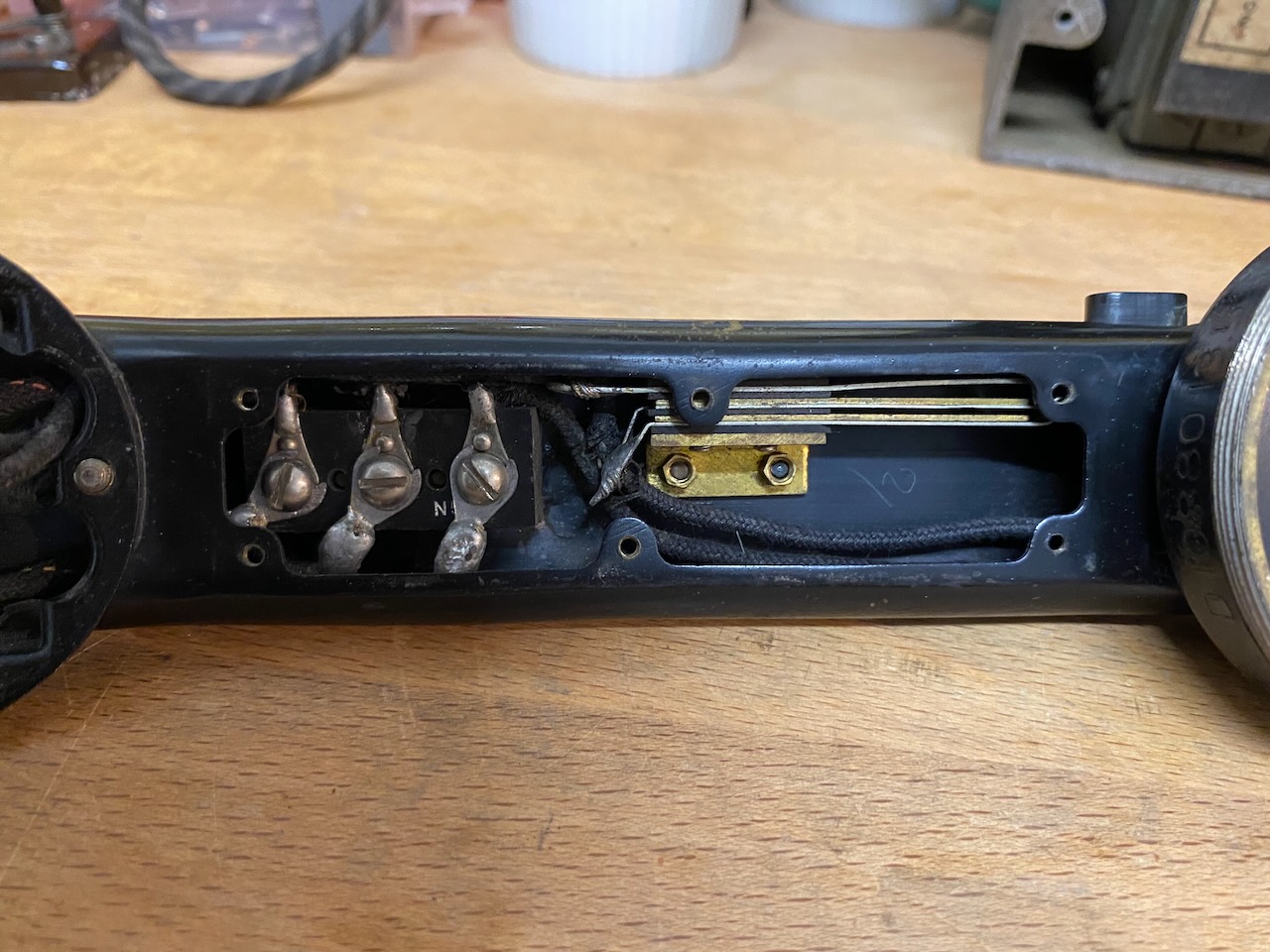
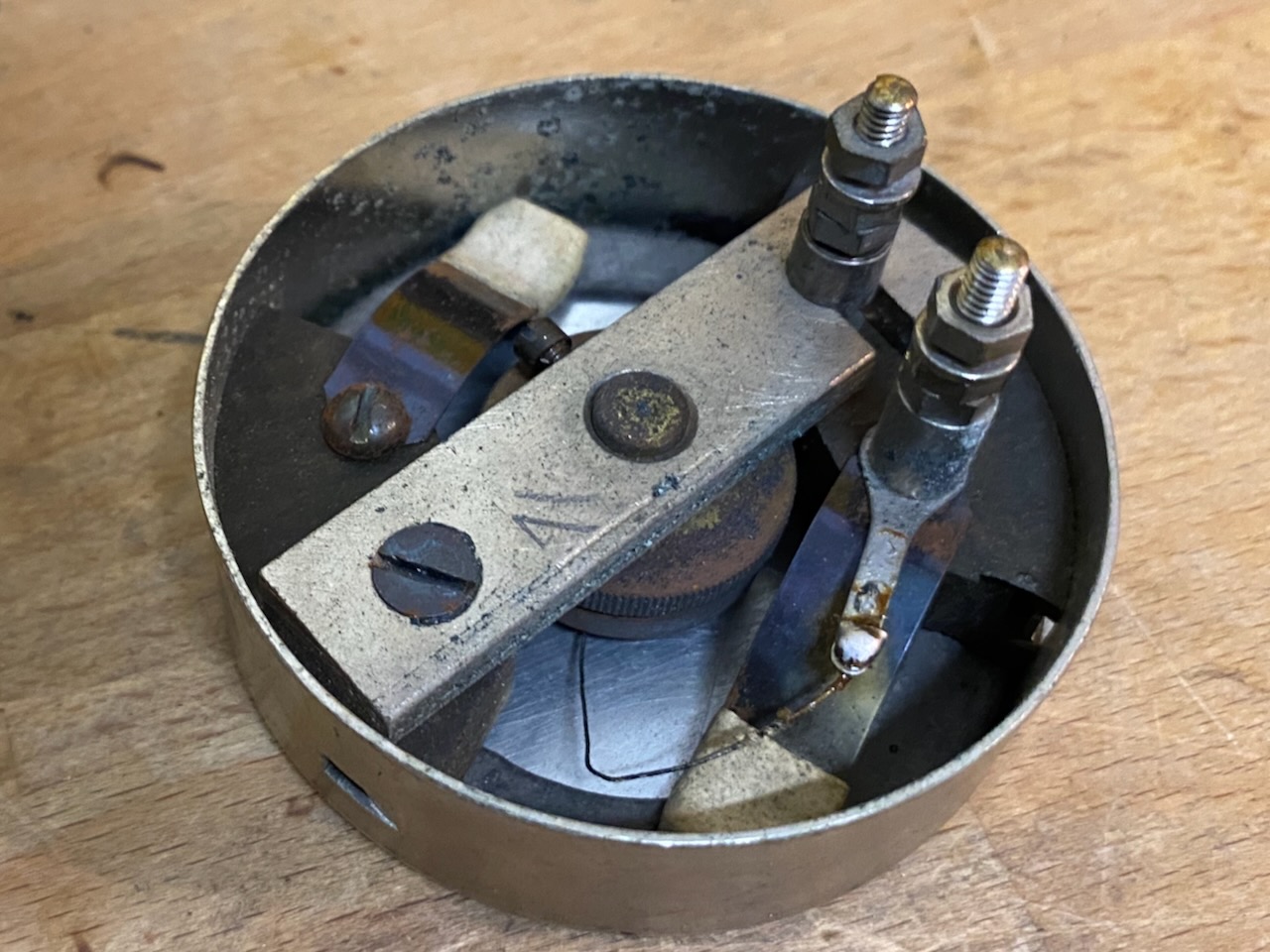
Solid-back carbon transmitter assembly.
Transmitter cup, D-Number D27549.
Transmitter mounted in its cup and connected.
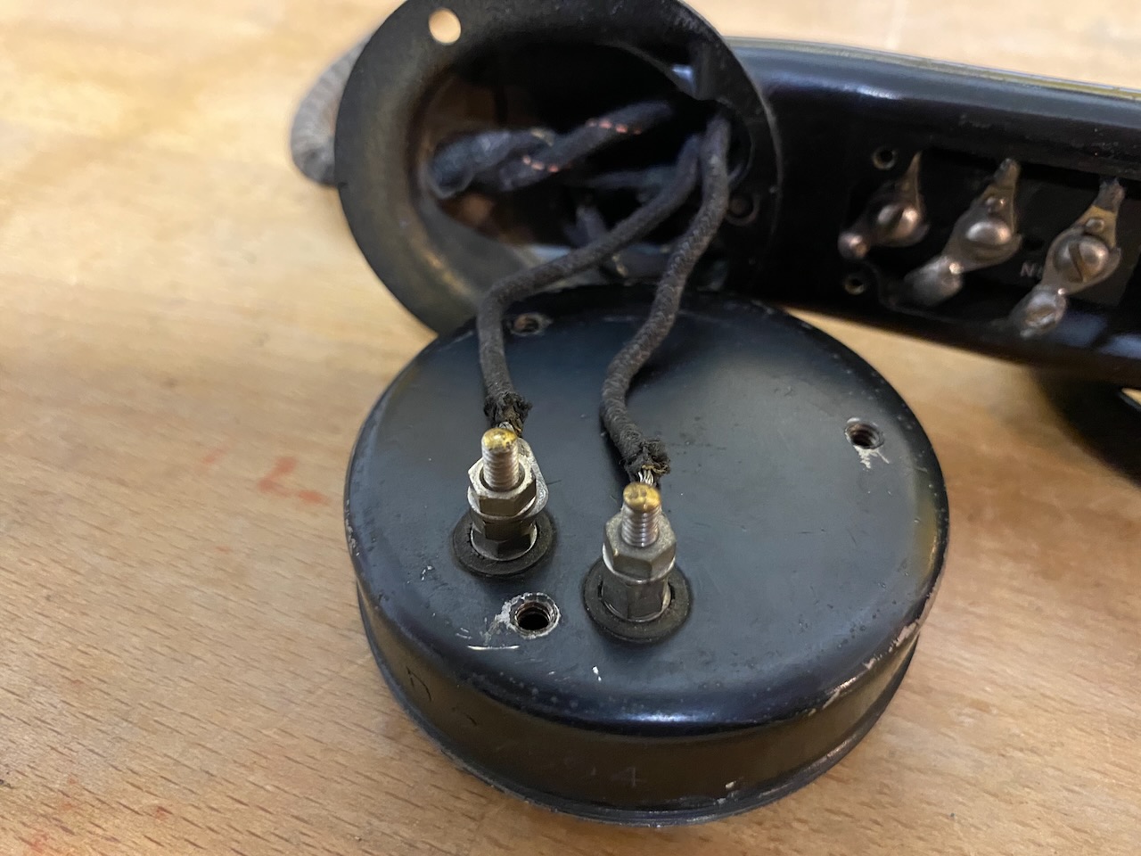
Partially assembled handset.
D-Number D24627.
Bears a patent date of 3 August 1903 [21].
Receiver side, D-Number D10880135.
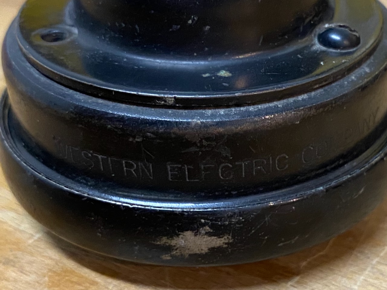
Western Electric Company marking on the handset.
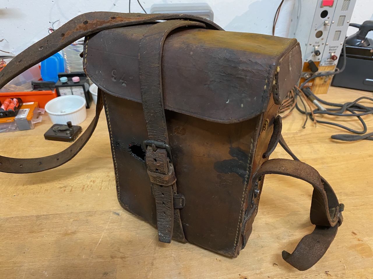
Empty leather carrying case.
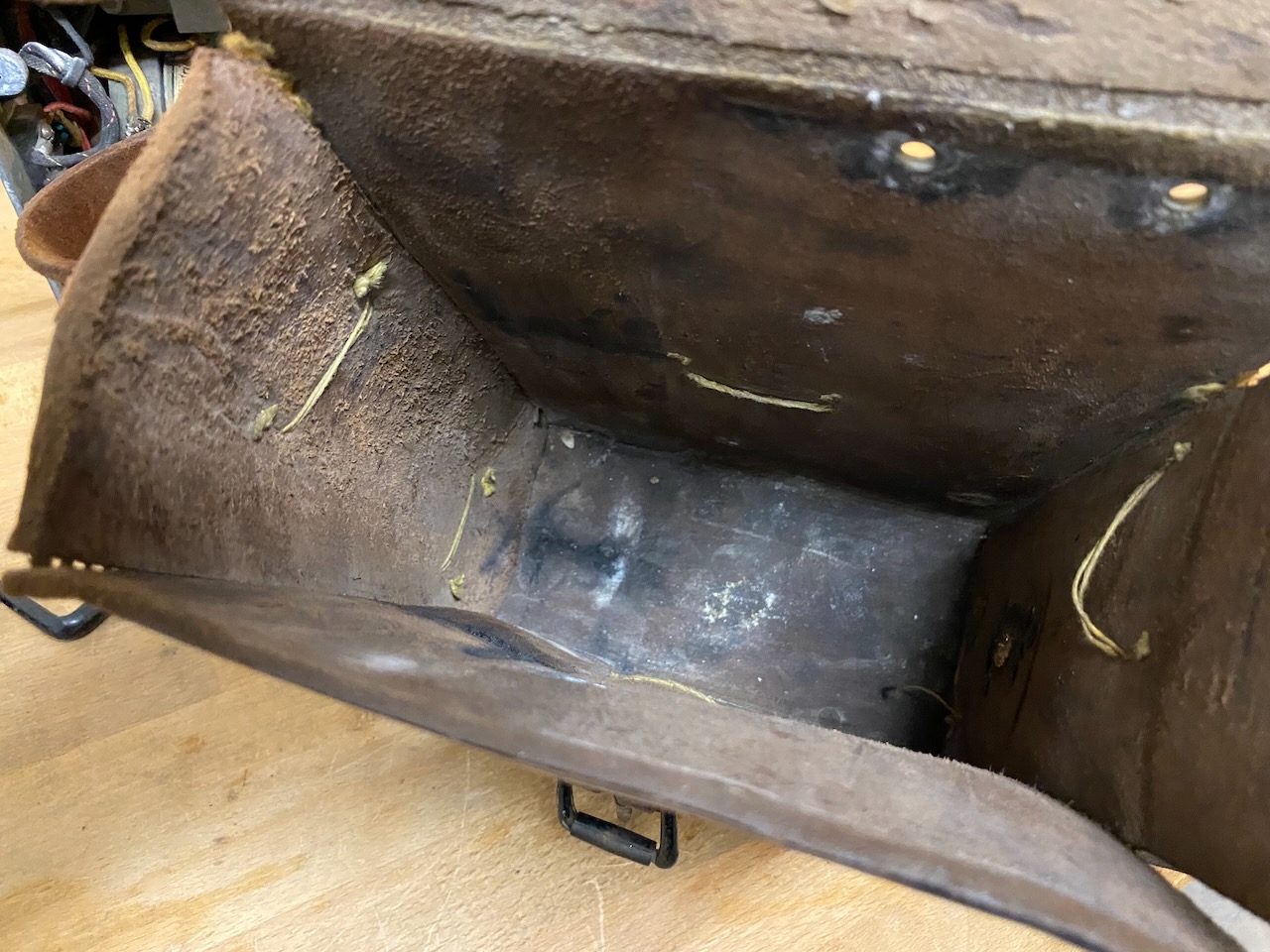
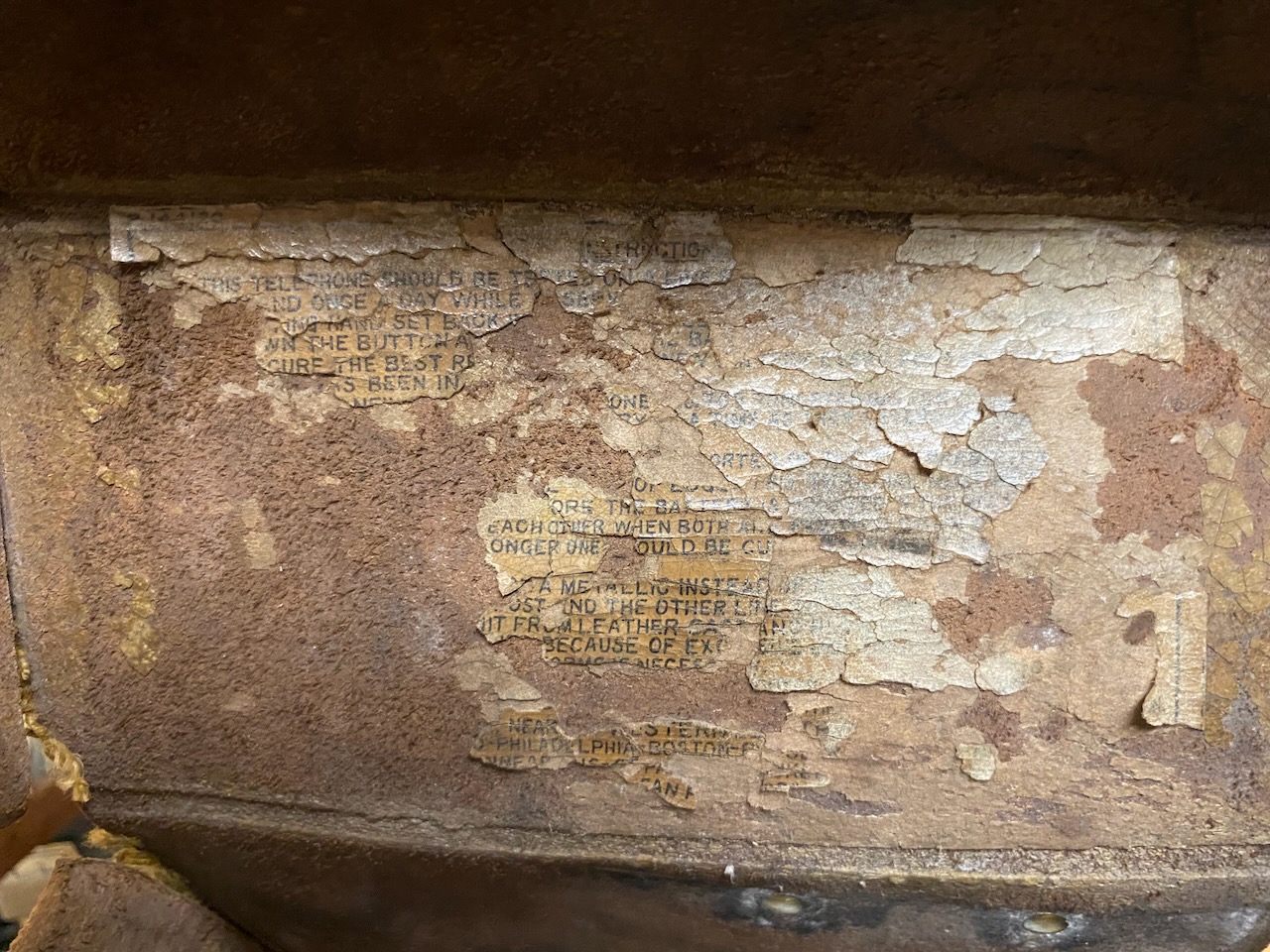
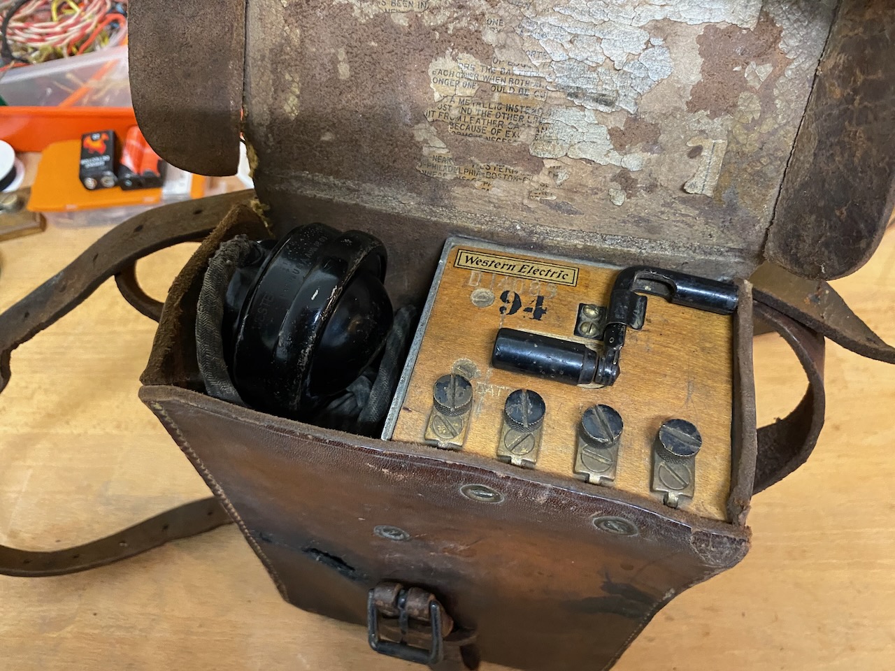
An instruction sheet was originally glued to the inside of the case lid.
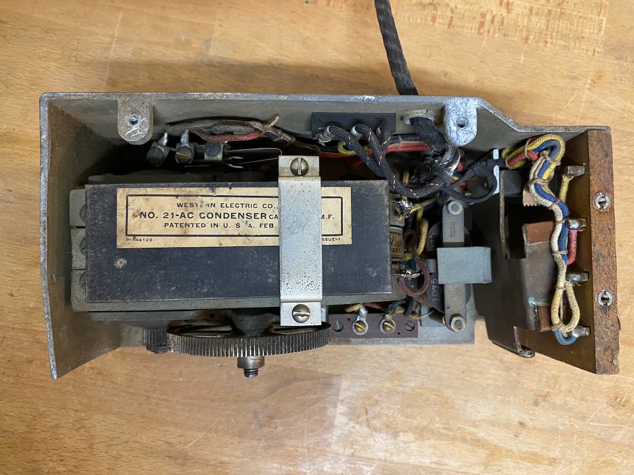
Front view of the chassis.
The large magneto is located behind the capacitor, with the ringer/buzzer and battery compartment to the right.
The induction coil is partially concealed by the wiring at the top.
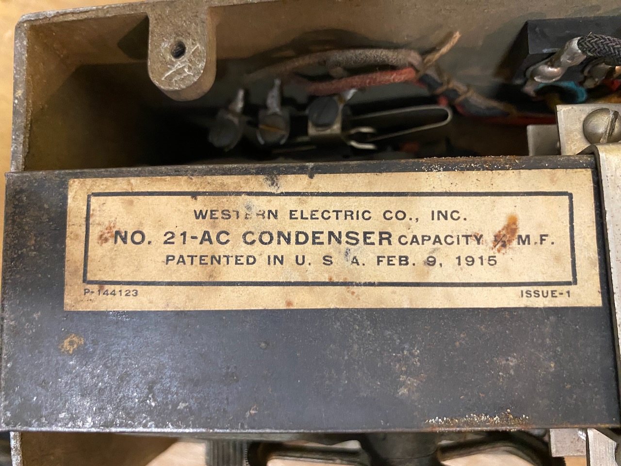
Capacitor with its retaining bracket removed to reveal the label.
Type No. 21-AC, 0.5 µF.
Bears a patent date of 9 February 1915 [22].
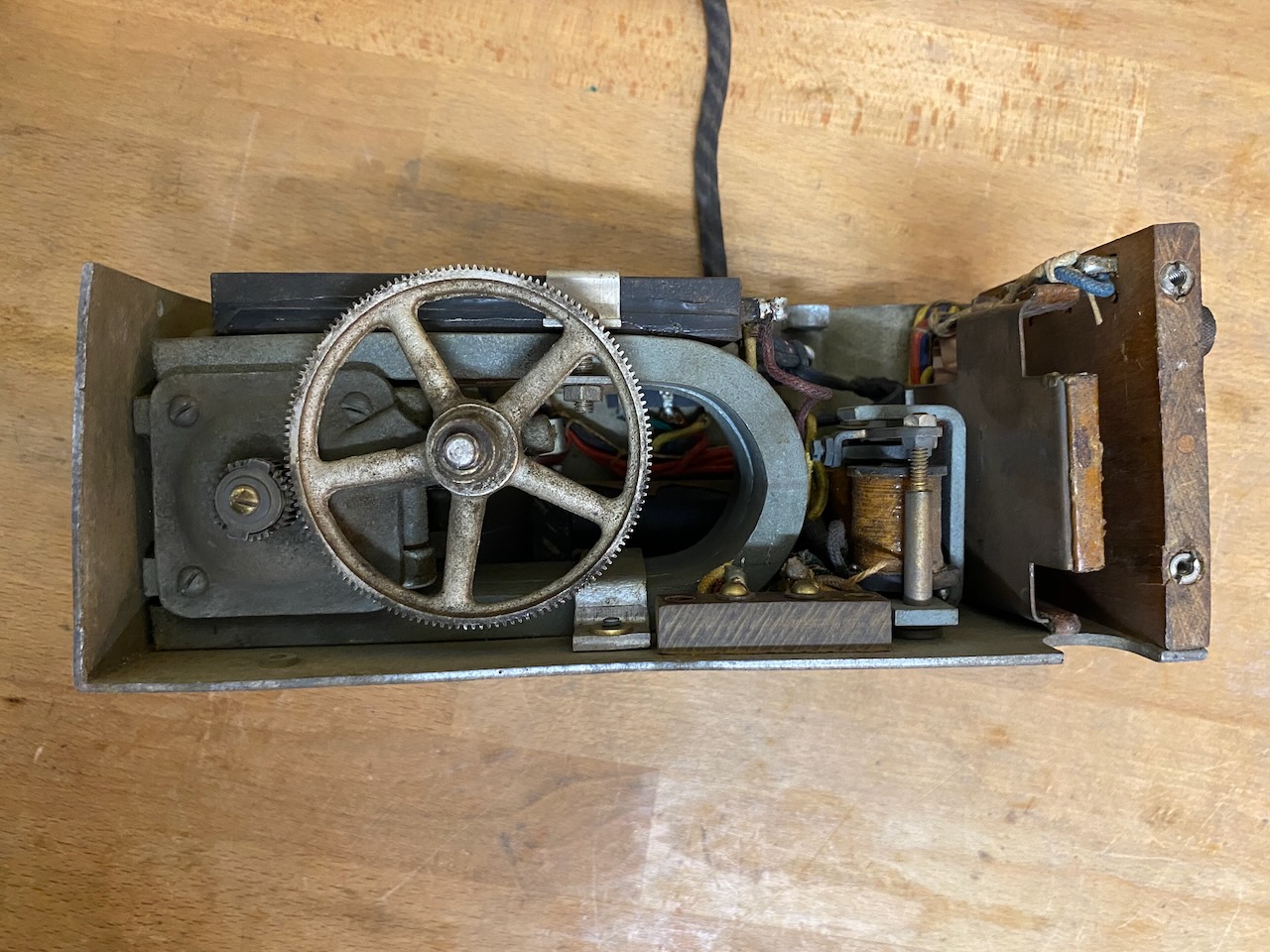
Front view of the magneto.
Rear view of the chassis.
Ringer/Buzzer detail, D-Number D21141.
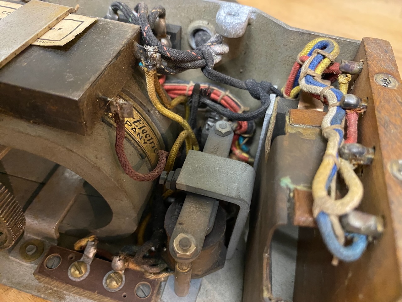
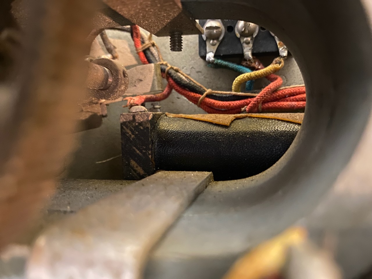
Induction coil located behind the magneto.
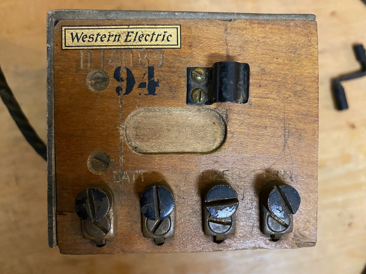
Top view of the chassis, D-Number D14089.
The binding posts for the external battery are on the left, with the "Line" and "GRD" (ground/earth) terminals on the right.
The bracket holds the magneto crank handle.
The number 94, also marked on the outside of the leather case, may be a unit or inventory number, although its exact significance is unknown.
Neatly arranged components.
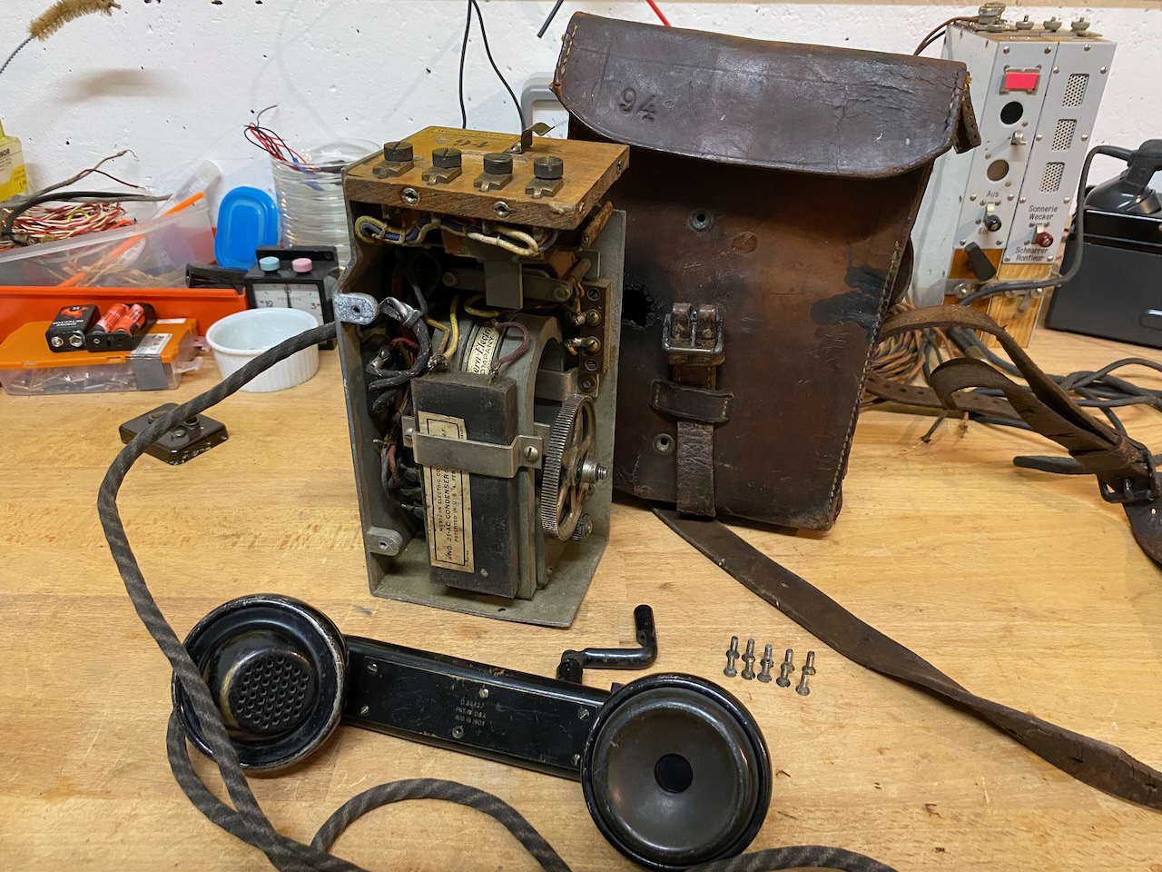
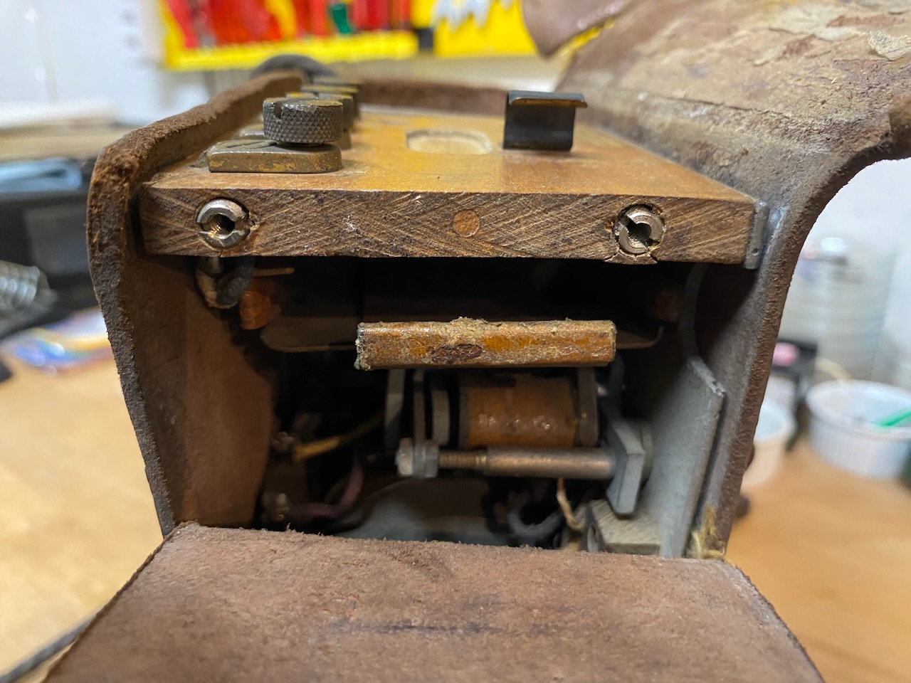
The leather case has an opening providing access to the battery compartment.
The compartment accommodates a type BA-9 battery (4.5 V flat battery) [3].
Ready for use.
All components stowed in the case.
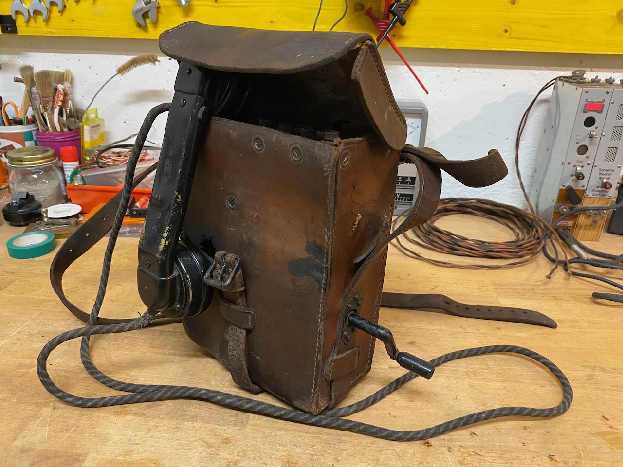
Ready for transport.
The front of the leather case has what appears to be a burn hole.
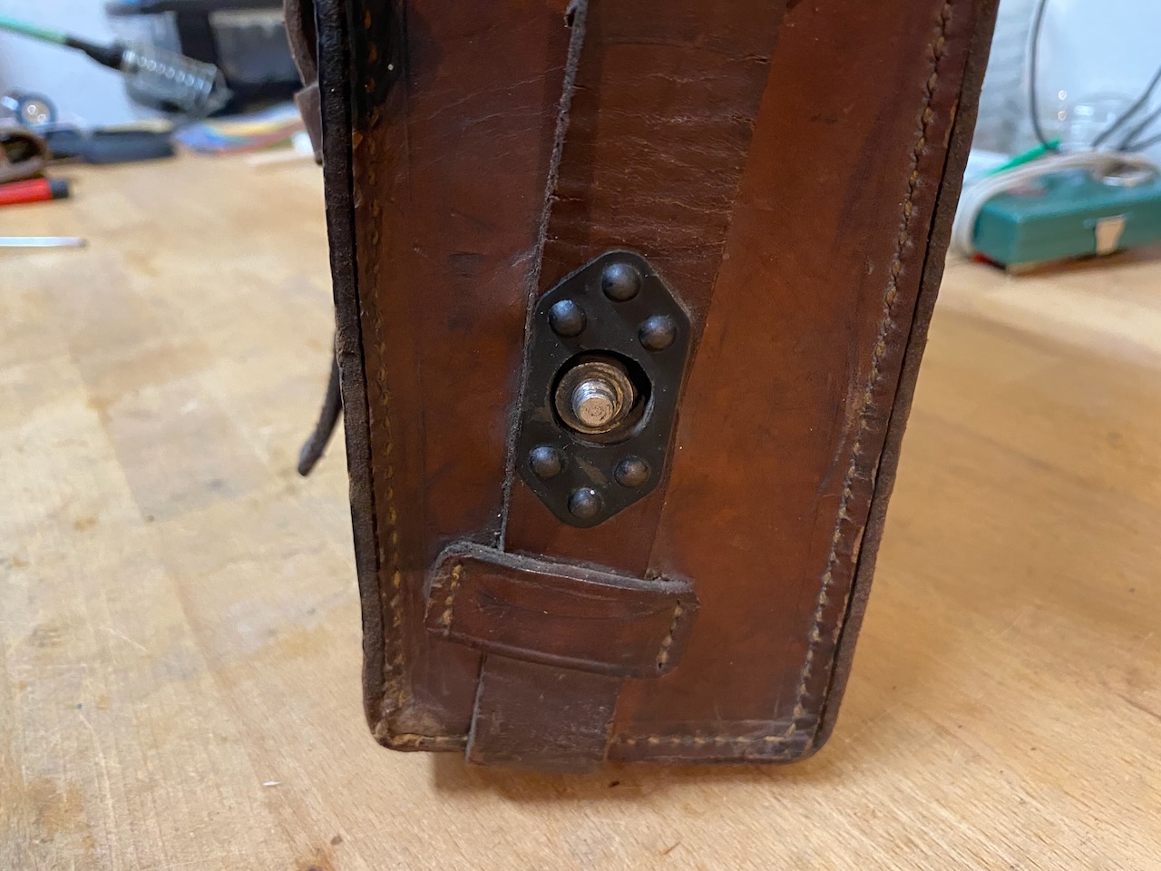
Right side of the case, showing the opening for the magneto crank handle.
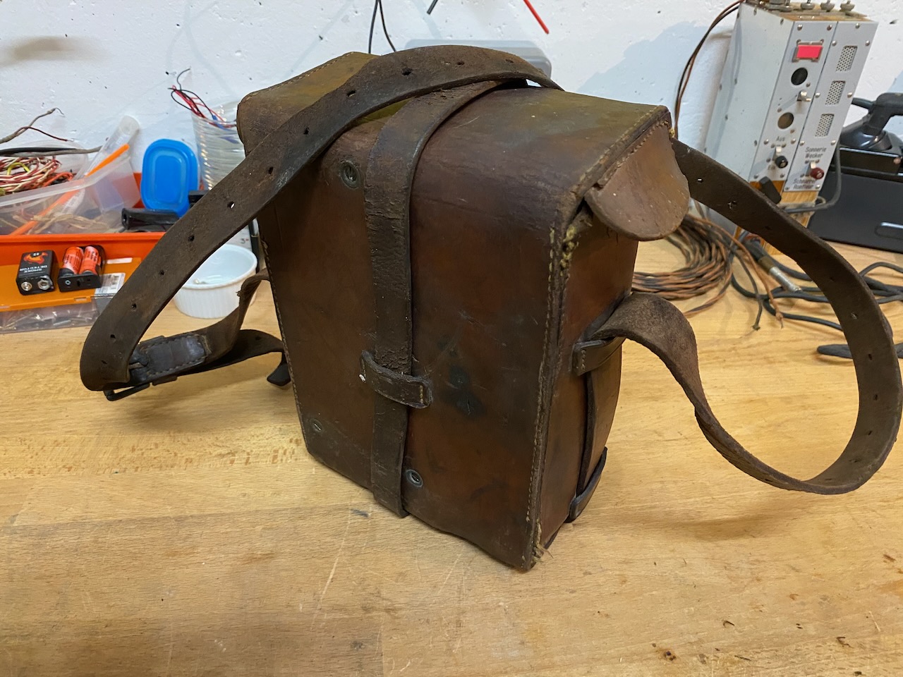
Rear view of the leather case.
Creative Commons Attribution-ShareAlike 4.0 International License